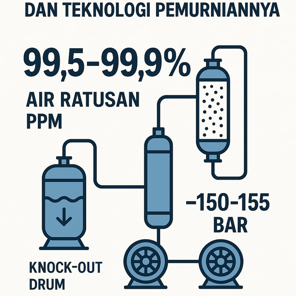
Modern urea synthesis demands CO₂ so pure it’s essentially pristine—99.5–99.9%—and dry to the low‑ppm range. Delivering that means knockout drums, molecular‑sieve dryers, multi‑stage compression to ~155 bar, and dense‑phase pipelines.
In the fertilizer business, the quiet workhorse behind urea is carbon dioxide—purified, dehydrated, and pushed to reactor pressure with almost clinical precision. Producers target very high-purity CO₂ (≈99.5–99.9%) to avoid poisoning the reaction. A commercial benchmark: Pupuk Indonesia sells CO₂ at ≥99.7% purity, with a water limit of 0.05% (500 ppm) and the balance (<0.3%) largely moisture (www.pupuk-indonesia.co.id). Similar standards apply for urea feed: essentially all non‑CO₂ components must be removed (id.scribd.com).
The stakes are not academic. Even small amounts of inerts (N₂, Ar) or combustible gases (H₂) dilute partial pressures and force extra recycles; higher inert levels are known to drop CO₂ conversion and raise vent ammonia (id.scribd.com). Any sulfides, oxygenates, or amines would corrode or deactivate downstream hardware. In short, the CO₂ delivered to the urea reactor should be ≥99.5% pure, with water and impurities in the low hundreds of ppm.
Many streams originate from amine sweetening and regeneration. The amine regenerator overhead may be cooled after compression to drop water; operators commonly reference amine solvent systems when describing this front end, not unlike an industrial amine solvent unit used for acid gas removal.
Contaminants and removal trains
Any residual moisture or organics must be scrubbed out. Water in CO₂ can form carbonic acid or hydrates at high pressure, causing corrosion and flow blockage (www.mdpi.com). The first stop is a knockout drum (K.O. pot: a vessel that condenses and separates liquids from gas) to remove condensed water and heavy hydrocarbons. Downstream, dehydration drives H₂O to tens of ppm using a Triethylene Glycol unit (TEG: a liquid desiccant) or a molecular‑sieve dryer (adsorption drying) (www.mdpi.com).
For pipeline‑grade or urea‑grade CO₂, published guidelines recommend keeping moisture below ~500 ppm—and even <100 ppm if trace acid gases are present—to avoid localized corrosion (www.researchgate.net). Heavy hydrocarbons (methane, ethane, propane, aromatics) are pared away by refrigeration or adsorption. Interstage intercoolers in the compressor train condense residual hydrocarbons for draining; if polishing is needed, operators add activated‑carbon beds, the kind of adsorption media seen in an activated‑carbon filtration step.
In practice, CO₂ from a clean amine plant has only ~0.03 mol% CH₄/C₂H₆ (as in reported cases), which is usually knocked out by cooling (www.cheresources.com). Finally, oxygen or nitrogen impurities (often <0.1%) are minimized by suppressing amine oxidation and tightening inert purge gas control.
Compression to urea reactor pressure
Purified CO₂ is compressed to the urea synthesis loop—typically ~150–155 bar (15–15.5 MPa) for modern high‑pressure reactors (id.scribd.com). Multi‑stage centrifugal or reciprocating compressors are used; at least 6–10 stages are common to reach >150 bar on CO₂ (epcmholdings.com). Each stage uses an intercooler (a heat exchanger between stages) to remove heat and condense any lingering water, with designs limiting discharge temperatures to ~80–95°C to balance power and materials (www.mdpi.com) (www.mdpi.com).
Design studies show that using more stages (5–6 intercoolers) can dramatically cut total power and heat removal requirements (www.mdpi.com) (www.mdpi.com). One academic CCS example compressed 2.45 Mt/y of CO₂ in 5 buzzard–cooling stages with a final interstage limit of 95°C, yielding overall power ~24 MW at full load (www.mdpi.com). At ~15 MPa discharge, the stream sits near the supercritical point (critical = 31°C, 73.8 bar), where CO₂ behaves as a dense fluid that is convenient for piping (epcmholdings.com). Compressor materials and seals are selected for CO₂ service (lubrication/oil‑free, compatible with any trace water).
Dense‑phase pipeline transport
Moving high‑pressure CO₂ across an integrated ammonia‑urea site—or to a nearby plant—calls for dense‑phase pipeline design (dense‑phase: high‑pressure, liquid‑like flow). Pipe material must retain ductility and toughness in CO₂ service; under pressure, CO₂ behaves like a high‑vapor‑pressure liquid, so fracture control matters (www.projectconsulting.com) (www.projectconsulting.com).
Engineers specify high‑strength carbon steel (e.g., X52) rated ≥200 bar, with stringent fracture‑control welding and inspection. Inline analyzers—gas chromatographs and moisture sensors—ensure the CO₂ meets spec (www.projectconsulting.com). The line is typically insulated and buried/driven in well to avoid dropping below the critical temperature, which would risk dry ice formation. Pressure ratings sit above the ~150 bar delivery target; relief and monitoring valves manage transients. Consistent with CCS guidance, moisture is kept to <500–1000 ppm to prevent corrosion or hydrate plugging (www.researchgate.net). Safety systems—non‑return valves, auto‑shutdown, vent headers—are standard.
Plant outcomes and industry direction
Modern integrated ammonia‑urea plants can save tenths of Mt CO₂ per year by recycling process CO₂. One Indonesian urea plant incorporated CO₂ capture and process improvements and cut ~4,180 tCO₂e/year (indonesia.un.org). The industry is trending toward “blue” ammonia and urea using captured CO₂, aligned with a national goal of avoiding millions of tons of emissions (indonesia.un.org) (indonesia.un.org).
The purification‑and‑compression designs above are mature: they routinely deliver >99.7% pure CO₂ for urea plants (www.pupuk-indonesia.co.id) and enable safe, energy‑efficient delivery to the synthesis loop. One example: a new plant in Indonesia converts 50,000 t/yr of urea off‑gas into liquid CO₂, producing food‑grade CO₂ at 99.7% purity (www.pikiran-rakyat.com) (www.pupuk-indonesia.co.id).
