A few months of impurity carryover once forced a 30 MW steam turbine offline; deposits alone cut output by ~5%. In combined-cycle plants, a 1% rise in moisture or solids can roughly mean a 1% efficiency drop—so operators are chasing purity at the parts‑per‑billion level.
Purity thresholds and performance risk
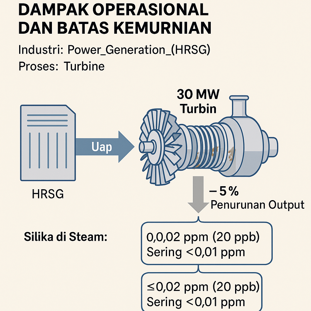
High‑purity steam—very low solids and negligible carryover—is foundational for turbine reliability. Case in point: just a few months of impurity carryover forced a 30 MW unit offline, with deposits cutting output by ~5% (watertechnologies.com). Solid particles drive mechanical blade erosion, while low‑pressure steam wetness compounds erosion and extraction losses (watertechnologies.com) (watertechnologies.com).
Boiler chemistry guidance ties poor steam purity to losses up to 5% efficiency or 20% capacity (watertechnologies.com). Because modern steam turbines use tight clearances, even a 1% increase in moisture or solids can roughly translate to a 1% drop in efficiency (mdpi.com) (watertechnologies.com).
To avoid those losses, combined‑cycle operators target steam total‑solids in the ppb (parts per billion) range. Silica in steam is generally kept under 0.02 ppm (20 ppb) and often below 0.01 ppm (watertechnologies.com). In practice, feedwater and drum chemistry control (including blowdown and pretreatment) holds steam contaminants like Na, Cl, and SiO₂ at single‑digit ppb. The target: very high steam purity—99.997%+ dry, with <10–30 ppb dissolved solids—to satisfy turbine OEM limits and prevent rapid wear (watertechnologies.com).
Consistently meeting those ppb‑level steam specs starts upstream, with the quality of make‑up water. Plants commonly specify RO (reverse osmosis) make‑up; the membrane train choice—such as integrated membrane systems—is a frontline decision that sets the chemistry baseline for the HRSG (heat recovery steam generator).
Steam drum internals and separation efficiency
At high pressure, gravity alone is not enough. In a high‑pressure drum at ~1000 psig, the steam/water density ratio is only ~20:1 compared to ~115:1 at 200 psig, making separation by buoyancy prohibitively slow (watertechnologies.com). Modern HRSG drums therefore use multi‑stage separation internals.
Primary separators—tangential swirl/cyclonic devices and baffles—apply inertia. The steam‑water mix enters curved channels; heavy droplets are spun out and returned to downcomers (watertechnologies.com). Secondary separation “steam scrubbing” polishes the steam: mesh or corrugated‑plate demister pads (wire media that coalesce mist) sit at low velocity directly under the steam outlet; remaining fine droplets impinge, coalesce, and drain away (watertechnologies.com).
In practice, one or more centrifugal (cyclonic) stages plus a final demister pad achieve the ~99.97% separation associated with ultra‑pure steam (watertechnologies.com) (watertechnologies.com). (As a design note, one high‑pressure drum patent describes tandem “visor” plates and drain slots that siphon films off stator vanes patents.google.com.) The coordinated layout of downcomers, baffles, cyclones, and mesh pads lets compact HRSG drums remove essentially all entrained water (watertechnologies.com) (watertechnologies.com).
Online chemistry monitoring and early warning
Because chemistry excursions accelerate damage, modern HRSGs continuously track steam and water chemistry at multiple points. Key measurements include conductivity (often “CACE”—cation conductivity after cation exchange), silica, sodium, oxygen, and iron at make‑up, condensate, feedwater, drum water, and steam (power-eng.com) (power-eng.com). For make‑up RO water, guidelines call for ≤0.1 µS/cm (microsiemens per centimeter) conductivity and <10 ppb silica (power-eng.com). That spec aligns with dedicated RO trains such as brackish-water RO and, when the source is marine, sea-water RO.
Other continuous targets include condensate sodium <2 ppb and dissolved oxygen (DO) <20 ppb (power-eng.com), and feedwater iron <2 ppb (power-eng.com). Online silica analyzers (fluoride electrode or photometric) and sodium analyzers (X‑ray fluorescence or ion‑selective electrode) provide early warning of boiler carryover or condenser leakage. A sudden rise in sodium or conductivity at the condensate pump discharge typically points to a condenser tube leak or blowdown fault—triggering a controlled shutdown before turbine damage (power-eng.com) (watertechnologies.com).
High‑sensitivity cation‑conductivity or tracer analyses (e.g., sodium tracer) can detect ppb‑level contaminants in steam (watertechnologies.com). The “CACE” method explicitly relies on a cation exchange step, the same basic ion‑exchange principle employed in many resin systems; in plant discussions of CACE, engineers often reference the underlying exchange mechanism (see ion-exchange systems) even though the analyzer is a dedicated instrument.
Industry authors call “on‑line chemistry monitoring a critical necessity” for HRSGs: without it, hidden leaks or foaming can slip by, causing unplanned outages (power-eng.com). In practice, aggressive programs have reduced chemistry‑related trips by ~50–70% in some combined‑cycle fleets (industry surveys) and help avoid losses on the order of tens of thousands of dollars per day of downtime.
Low‑pressure end design against wet steam
Even with very pure steam, some moisture condenses in the low‑pressure (LP) end. Designers counter moisture with flow‑path features and materials. Large turbines often employ in‑cylinder moisture separators/reheaters (MSRs): between intermediate‑pressure (IP) and LP sections, a divergent‑stage separator extracts water and the steam is reheated. In smaller combined‑cycle units with a single LP cylinder, the focus shifts to last‑stage geometry and erosion‑resistant materials.
One approach: drain the liquid before it hits the rotor. A documented diaphragm concept mounts overlapping shroud “visors” with a drain slot and holes, funneling liquid shed from the stator out of the steam path into collectors (patents.google.com). Blade profiles in the last rows are also shaped to fling droplets outward or coalesce them into drainable films.
Materials complete the defense. LP blades commonly use high‑chrome stainless or cobalt‑based Stellite alloys, and many are coated via HVOF/HVAF (high‑velocity oxy‑fuel/air‑fuel) thermal spray with tungsten‑carbide/cobalt‑chrome. These coatings can reach 1,400–1,600 HV hardness and are essentially impermeable, extending blade life markedly under droplet impact (kermetico.com). One industry summary notes that “HVOF tungsten carbide… and Stellite‑type coatings have been chosen among the best” for wet‑steam protection (kermetico.com). In the field, these drain features and hard coatings have multiplied erosion life several‑fold versus unprotected steel. The result: by combining mechanical separation at the diaphragm with abrasion‑resistant blades, modern turbines virtually eliminate low‑stage failure from wet steam and protect long‑term reliability (watertechnologies.com).
Sources and technical references
Authoritative industry references and research were used throughout. For steam purity and effects, see the IAPWS guidance and industry handbooks (watertechnologies.com) (watertechnologies.com) (watertechnologies.com). Drum separator design is detailed in boiler‑water literature (watertechnologies.com) (watertechnologies.com). Monitoring recommendations come from ChemTreat/Power Engineering (power-eng.com) (power-eng.com). Turbine erosion studies appear in power‑plant engineering reports (watertechnologies.com) and patent literature (patents.google.com), with coating performance summarized by surface‑engineering sources (kermetico.com).
