Ammonia synthesis runs hot and under crushing pressure, but the money is made in the cold end — multi‑stage refrigeration that drops loop gas to –20 to –30 °C and strips out nearly all the product. The choice of refrigerant and the design of those chillers decide yield, energy, and even regulatory exposure.
Industrial Haber–Bosch units push nitrogen and hydrogen through iron catalysts at roughly 15–25 MPa (150–250 bar) and ∼400 °C, yet single‑pass ammonia (NH₃) conversion is typically less than 20% (pubs.rsc.org) (pubs.rsc.org). The fix is counterintuitive: go sub‑zero. Plants recover heat first (feed preheat, steam generation), then use refrigeration to about –20 to –30 °C so liquid NH₃ condenses and separates.
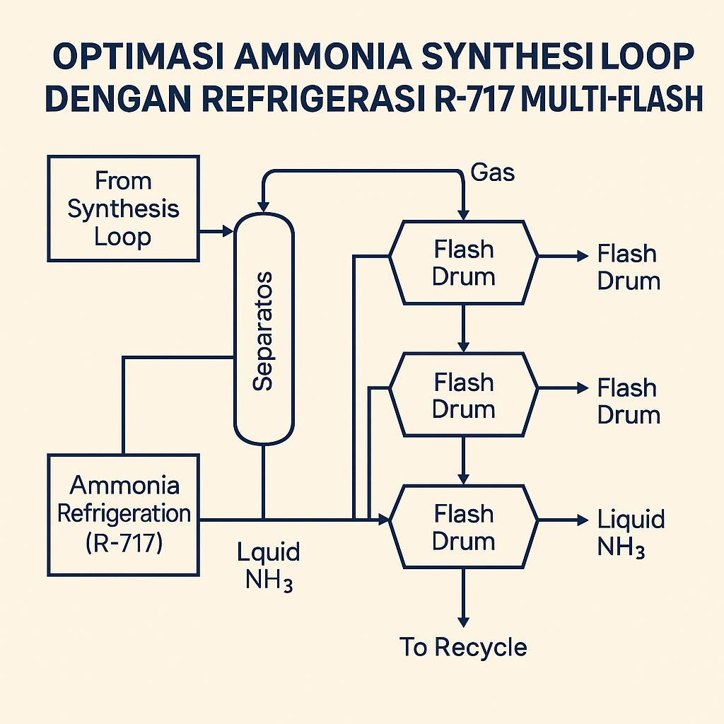
One pro forma design chilled reactor effluent at 100 bar to –23 °C, flashed it to 90 bar to drop out a first cut of liquid ammonia, then cooled the overhead further to –27.5 °C and flashed again to recover more NH₃ (www.owlnet.rice.edu) (www.owlnet.rice.edu). The combined ammonia‑rich bottoms were then warmed to approximately –5 °C and flashed at around 15 bar to strip remaining inerts (impurities like H₂, N₂, CH₄) — vaporized impurities exited as purge — yielding high‑purity liquid product (www.owlnet.rice.edu).
The three‑stage flash scheme — two high‑pressure stages and a final low‑pressure “washout” — is typical of modern large plants, achieving >99.5 mass% NH₃ in product in one modeling case (www.owlnet.rice.edu) while leaving only ~3.8% NH₃ in recycled syngas (synthesis gas) (www.owlnet.rice.edu). By contrast, a simpler simulation predicted only ~98% purity, underscoring how detailed design and accurate phase data matter (www.owlnet.rice.edu).
Overall conversion is lifted by recycling roughly 70–80% of unreacted syngas, with a purge of a few percent to bleed off accumulated inerts — and that purge is taken after NH₃ removal so it contains very little product (www.owlnet.rice.edu) (www.owlnet.rice.edu) (www.owlnet.rice.edu). All in, the loop’s refrigeration and separation section — in a 1,000 tph (tonnes per hour) plant — might cost on the order of $2.1 million (www.owlnet.rice.edu) and enables >90–95% net conversion even with only ~15–20% per‑pass yield.
Thermodynamics and refrigeration duty
The ammonia production stage condenses product at about –25 °C to –30 °C after recovering heat for the plant, typically via an ammonia refrigeration cycle (pubs.rsc.org). In practice, the closed‑loop NH₃ (anhydrous ammonia, refrigerant designation R‑717) system uses multi‑stage compressors — often two stages with intercooling — and a water‑cooled condenser at roughly ambient temperature to supply the –25 to –30 °C cooling lift (www.owlnet.rice.edu).
That cold end is energy‑intensive: refrigeration compressors alone consumed on the order of 6.6 GJ per tonne of NH₃ in one analysis, about 60% of the synthesis‑loop energy (pubs.rsc.org). Even a 1% improvement in condensation in a 1,000 t/d plant could lift output by ≈3.7 t/d of NH₃ — a swing worth millions annually, depending on price levels.
Refrigerant choices and regulations
Commercial synthesis‑loop refrigeration almost exclusively uses ammonia (R‑717) as the refrigerant. It brings high latent heat — approximately 1.15 MJ/kg at –30 °C — and strong heat‑transfer performance with essentially zero ODP (ozone‑depletion potential) and GWP (global warming potential), making it more efficient and environmentally benign than legacy halocarbons (www.danfoss.com) (handbook.ashrae.org).
Regulatory trends reinforce that choice. Indonesia has banned ozone‑depleting HCFCs (e.g., R‑22) in industry starting 2015 (www.sewa-ac.com) and, as of 2023, is committed to phasing down HFCs (hydrofluorocarbons) under the Kigali Amendment with a baseline set in 2024 and targets to cut 80% by 2045 (ppid.menlhk.go.id) (ppid.menlhk.go.id). Of the HFCs imported for cooling in 2015–19, many have extremely high GWPs, including R‑404A (GWP ≈3,922) and R‑410A (≈2,088) (ppid.menlhk.go.id).
Alternatives like CO₂ (R‑744) or hydrocarbon refrigerants can be used in special cascade cycles (CO₂ for very low temperatures), but none matches ammonia’s efficiency at large scale in this service. In practice, many fertilizer plants simply bleed off some purified NH₃ to serve as the R‑717 refrigerant for the chiller — one design notes “a portion of the product ammonia is used as refrigerant in the loop” (www.owlnet.rice.edu). Compared with halocarbon systems, ammonia refrigeration is more energy‑efficient (roughly a few percent higher COP, the coefficient of performance) and lower cost (smaller pipe sizes and cheaper refrigerant) (www.danfoss.com). Ammonia is relatively toxic, but its distinct odor and lighter‑than‑air behavior allow robust safety measures; by contrast, HFCs are inert but climate‑damaging.
Multi‑stage chilling and separation design
Multiple cooling and flashing stages maximize NH₃ recovery and lower duty. In the ammonia‑refrigeration example, two high‑pressure cooling stages (–23 °C then –27.5 °C) removed most NH₃ before a final low‑pressure flash that purged inerts (www.owlnet.rice.edu) (www.owlnet.rice.edu). Condensing roughly 80–90% of the NH₃ in the first, moderately cold stage means the second stage only handles the remainder, cutting incremental refrigeration load; a single flash would demand much colder evaporators or extreme compressor ratios.
The first flash often runs near reactor pressure, the second at slightly lower pressure, and the final at much lower pressure (tens of bara). One study combined the bottoms of the first two high‑pressure drums, reheated that liquid to about –5 °C, then flashed to 15 bar to produce a very pure NH₃ distillate (www.owlnet.rice.edu). Residual dissolved gases — mainly Ar and CH₄ — are removed in that final “wash” flash.
The resulting purity is high. In the modeled design above, product streams carried only ~0.02% N₂ and ~0.03% H₂, yielding 99.7 mol% NH₃ in the product (www.owlnet.rice.edu) (www.owlnet.rice.edu). Ambitious unit designs have explored cascade refrigeration — for example, a CO₂ receiver cooled via an NH₃ loop — but those add complexity; most plants stick with plain R‑717 refrigeration.
Recovery efficiency and loop economics
Efficient separation is central to ammonia yield and compressor power. Any NH₃ left in recycle must be recompressed — wasting energy — and it “poisons” the iron catalyst if reintroduced (www.owlnet.rice.edu). Designs aim to leave only a few percent NH₃ in recycle; the example above held recycle at 3.8% NH₃ (www.owlnet.rice.edu). In a 1,000 t/d case, 1,000.5 t/d NH₃ was recovered from 1,190.6 t/d after the reactor — product at 99.5% purity on a mass basis (www.owlnet.rice.edu).
Purge strategy matters too: taking a few‑percent purge after NH₃ removal minimizes product loss in the purge (www.owlnet.rice.edu). With multi‑stage cooling and smart separation, plants reliably hit >99% ammonia recovery and >99.5% purity in product streams (www.owlnet.rice.edu) (www.owlnet.rice.edu).
Source notes
Key technical data are drawn from industry studies and reviews. Fiat and coauthors report typical Haber–Bosch loop conditions (400 °C, 150 bar) and –25 °C condensation (pubs.rsc.org); Smith et al. (2020) note refrigeration alone uses ~6.6 GJ/t‑NH₃ (pubs.rsc.org). Design case studies (Voltron Inc.) give detailed flash temperatures and purity — –23 and –27.5 °C stages, 99.5% NH₃ product (www.owlnet.rice.edu) (www.owlnet.rice.edu). Regulatory context (Montreal/Kigali) underpins refrigerant choice: Indonesia banned HCFCs from 2015 (www.sewa-ac.com) and is phasing down HFCs (ppid.menlhk.go.id). All cited figures and outcomes are drawn from these sources to inform engineering and investment decisions.
