Automotive cathodic electrodeposition (e‑coat) is a deceptively delicate process built on a dilute paint bath that is typically about 85% water and 10–15% polymer/pigment solids (percentages per finishing.com). Running it well is a quality and compliance exercise: side‑stream ultrafiltration (UF), regular membrane cleaning, biocidal control of microbes, and anolyte/catholyte circuits for pH and conductivity work together to boost transfer efficiency, curb waste, and meet discharge limits. The UF loop, in particular, functions as the “efficiency engine” of the line, continuously skimming water and low‑molecular contaminants while returning expensive paint solids to the tank (Finishing & Coating; JMX).
Membrane permeate often feeds rinse stages; one installation closed its rinse loop and eliminated about 9 million gallons (34×10^6 L) of deionized water per year, saving $275,000 (Solecta). In parallel, biocides keep bath waters sanitary (finishing.com), and dedicated anolyte/catholyte circuits control the chemistry that governs film build and defect rates (Membracon; Ecoatline).
Ultrafiltration: solids recovery and clean rinses
UF (ultrafiltration) uses crossflow membranes to remove water and dissolved volatiles while retaining and returning paint resin/pigment to the bath, typically removing >95–99% of suspended paint solids (Finishing & Coating; JMX). One supplier reports recovery “up to 99% of the paint solids,” sharply improving economics by recycling solids rather than losing them to drain (Solecta). UF also stabilizes bath conductivity by removing ionic contaminants; permeate for final rinses should remain <50 µS/cm (microsiemens per centimeter) (PPG; Ecoatline).
Capacity is tracked by permeate flux. A new 7.6″×40″ “7640” spiral UF element typically produces ~4.5 gpm (≈17 L/min); when flow drops below ~1 gpm (~4 L/min), it’s considered spent (Finishing & Coating). Design throughput aligns to coating rate: about 2 L of UF permeate per m² of coated surface is needed, so at 30 m²/min the UF must supply ~60 L/min clean water for rinsing (JMX). In many cases, combining UF with electrodeionization or reverse osmosis (often called “EDRO”) raises paint‑transfer efficiency to over 99.8% (JMX). Where it fits the plant’s train, modular packages such as ultrafiltration skids and integrated membrane systems provide the needed permeate quality and flow.
UF system design and operation
A typical UF skid uses a feed pump, prefilters, and multiple spiral elements; “duplex” or “quadruplex” configurations provide redundancy, and a dual‑train system might have 16 elements in total (JMX). Bath feed is commonly bag‑filtered at ~25 µm to catch oversize debris; robust prefiltration prevents channel clogging on the UF (Finishing & Coating). As UF concentrates solids, the reject can approach ~15–30% by weight; this thick “paint slime” is periodically dumped as sludge.
Because resin molecules and pigments accumulate at the membrane face, they form a gel layer—described as “double parked”—while the aqueous fraction passes (Finishing & Coating). UF permeate quality is typically pristine; beyond e‑coat, studies on carwash water found UF removed >60% of surfactants and nearly all suspended solids, illustrating the selectivity of the process (MDPI).
Membrane maintenance and cleaning
Preventive care is cheaper than running a “sick” UF. Systems use periodic chemical cleaning‑in‑place (CIP): circulating acid (pH ≈2) or caustic solutions to dissolve deposits. Once a thick gel forms, cleaning accesses only the most clogged front side of the ~30 m² spiral surface, so operators aim to clean before severe blockage (Finishing & Coating). Many plants run short backwashes (reverse flow) every 30–120 minutes and schedule thorough chemical cleans weekly or monthly. Dedicated chemistries, like membrane cleaners, support repeatable CIP without damaging elements.
Operational discipline matters: prefilters protect spacer channels; soft‑start pumps avoid pressure spikes; throttling feed lines or abrupt power cycles can damage elements (including telescoping), so tagged valves and checklists are standard practice (Finishing & Coating; Finishing & Coating). Falling permeate flow is the primary warning of fouling; some skids add differential‑pressure gauges, and daily logging of UF metrics helps catch trends early (Finishing & Coating). Several suppliers design elements for frequent backwash—for example, PPG’s single‑layer UF polymer for e‑coat applications (PPG).
Microbial control and biocides
Water‑based e‑coat circuits can harbor bacteria, algae, and fungi—especially in anolyte/water loops—leading to sludge, biofilms, clogs, and odor. Many operations dose broad‑spectrum biocides in the anolyte (and sometimes the bath) on a schedule; reported practices include 0.2–0.3% weekly additions of Kathon (isothiazolinone), glutaraldehyde‑based systems (THPS), silver‑based biocides, or periodic hydrogen peroxide flushes at 0.2–0.5% (finishing.com; finishing.com). Some plants have also used silver nitrate to sterilize anolyte recirculation (finishing.com). The cost of biocide is small compared to the risk of fouled UF pumps or production stoppage.
Biocide dosing is often paired with flush‑and‑replace: circulating a sanitizer for hours, then draining and refilling the anolyte weekly or biweekly; seasoned managers plan full anolyte replacement every 2–4 weeks (finishing.com). Because makeup DI can seed organisms, UV sterilizers on the DI line feeding the anolyte help prevent colonization (finishing.com). Packaged options like industrial biocides and in‑line UV sterilization fit this hygiene strategy.
Bath suppliers typically include biocides in the main e‑coat bath, but heavy contamination can still reduce cure temperature and cause gloss defects (finishing.com). Notably, one forum reported algae formation when anolyte resistivity dropped (i.e., conductivity rose and pH fell), underscoring the link between chemistry control and microbial risk (finishing.com).
Anolyte/catholyte: pH and conductivity control
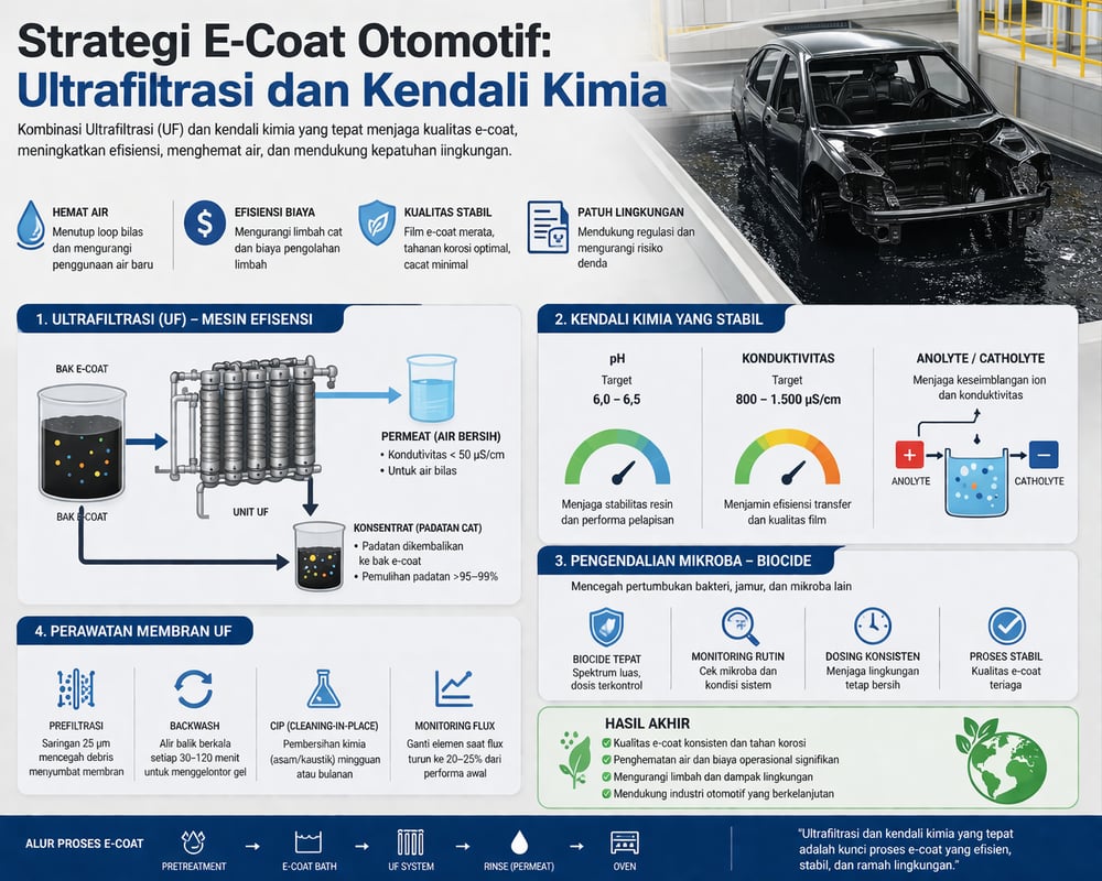
In cathodic e‑coat, the anolyte is a separate recirculating acid solution that washes the anode cells; it’s usually deionized water acidified to pH≈2–3 with supplier‑specified “pH controller” acids (often phosphoric or sulfonic), while the paint tank itself functions as the catholyte (Membracon). Anolyte flow carries away H⁺ generated at the anodes, keeping the main bath near its buffered pH (commonly ~5.7–6.0 per paint supplier specs). The anolyte pH tends to fall (more acidic) over time; operators monitor pH and conductivity and add DI water to dilute back into range, often with automation (Membracon; finishing.com). Metering via a dosing pump helps maintain tight setpoints.
Target conductivities are tight. The anolyte can run from ~300–5,500 µS/cm depending on formulation (forum example) (finishing.com), with per‑cell anode flows often 1–3 L/min (Membracon). The paint bath typically targets ~1,200 µS/cm (±300); high bath conductivity raises throwing power but can trigger defects, while too low impairs coverage (Ecoatline; Ecoatline). UF permeate used in rinses should be <50 µS/cm, and any DI/RO makeup should be essentially pure (target <5 µS/cm) to avoid creeping the bath out of spec (Ecoatline; Ecoatline). Plants often pair UF with RO or electrodeionization; modular units such as EDI or bundled RO/UF trains are common in new builds.
Interlocks are used to keep steady‑state: for example, exceeding an upper bath threshold (~1,500 µS/cm) can trigger an automatic permeate flush or addition of fresh makeup; a pH rise can call for more acid. The objective is an ion balance: plating introduces charged species that UF and makeup control remove, holding conductivity around the target window (Ecoatline).
Conductivity setpoints and film build
When the ecosystem holds, typical coats deposit ~20–25 µm at 20°C with uniform finish; straying outside conductivity limits (e.g., >1,500 µS/cm) can cause thick films (>35 µm) and defects, while too low (e.g., <900 µS/cm) leads to insufficient thickness (Ecoatline). Conductivity “directly influences coating quality,” so frequent testing and automated metering are justified (Ecoatline).
Regulatory and economic context
Beyond operations, water and waste costs make the case for optimization. Reports note that modern UF/RO integration can slash fresh water usage by 80–90% compared to older dilute systems; one Solecta client eliminated 34×10^6 L/year (9MM gallons) of DI water for ~$275,000 in annual savings (Solecta; Solecta). Improving paint transfer from ~92% to >99% translates to thousands of liters of paint saved annually at volume, often paying back UF capital in <1–2 years. By contrast, a fouled UF element that forces a drain‑and‑refill can cost tens of thousands per event when paint loss, downtime, and wastewater fees are tallied.
Regulators are watching. In Indonesia and elsewhere, rules such as Environmental Law No. 32/2009 impose strict wastewater standards, with penalties up to IDR 15 billion (≈USD 0.95 million) for violations; more than 80% of Indonesia’s rivers are reported polluted (HAS Environmental; HAS Environmental). Closed‑loop rinsing and on‑spec permeate—delivered by UF and allied trains—are as much about compliance certainty as cost.
Technical notes and sources
Key UF figures: new 7640 elements at ~4.5 gpm (≈17 L/min) with planned replacement at ~1 gpm (~4 L/min); rinse design at ~2 L permeate per m² coated; solids recovery up to ~99% and a documented 34×10^6 L/year DI water saving (~$275k/year) (Finishing & Coating; JMX; Solecta; Solecta). Anolyte composition and function: acidic DI at pH≈2–3 to wash anode cells, with per‑cell flows often 1–3 L/min; bath pH around 5.7–6.0, anolyte conductivity examples at 300–5,500 µS/cm (Membracon; finishing.com). Conductivity targets: UF permeate <50 µS/cm, DI/RO <5 µS/cm, bath around ~1,200 µS/cm (±300), with film build sensitive to excursions (>1,500 µS/cm can yield >35 µm; <900 µS/cm risks thin films) (Ecoatline; Ecoatline; Ecoatline; Ecoatline). Additional technical context is available from supplier notes (PPG) and academic reviews (ScienceDirect).
Bottom line: when UF, membrane upkeep, biocidal hygiene, and anolyte/catholyte controls are aligned, e‑coat lines achieve near‑complete paint recovery and closed‑loop rinsing while holding tight pH/conductivity windows that minimize defects (Solecta). In this calculus, small investments in cleaning cycles and chemistry pay off in yield, uptime, and compliance certainty (HAS Environmental).
