As produced water surges and discharge limits tighten, operators are turning to compact membrane bioreactors that shrink footprint while pushing effluent quality toward reuse. The pitch: gravity tanks out, ultrafiltration in—without sacrificing reliability offshore.
Offshore rigs don’t get to choose their wastewater. The mix swings from oil-in-water emulsions and drilling mud brines to detergent-laced wash-down streams—often stabilized by the very chemicals used to keep platforms running. Reviews catalog produced water as dispersed oil, dissolved organic solvents, suspended solids, plus biocides and corrosion inhibitors that stabilize emulsions (MDPI). As fields age, variability grows extreme: in mature provinces such as Indonesia, “the volume of produced water is more than 8 million barrels per day” and can reach up to ~90% of fluids (ResearchGate).
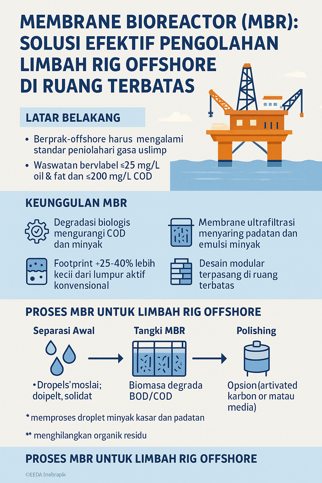
The regulatory screws are tightening too. Indonesia’s Ministry of Environment Regulation No.19/2010 caps produced-water effluent at ≤200 mg/L COD (chemical oxygen demand, a measure of oxidizable organics) and ≤25 mg/L oil & grease (O&G) (ResearchGate, ResearchGate). Many offshore regimes demand O&G <10–30 mg/L (e.g., 42 ppm limit in UKCS). Historically, operators leaned on gravity/API separators and reinjection—focused mainly on free oil (ResearchGate). Today, sub‑25 mg/L O&G and COD controls drive advanced tertiary treatment. Published data show a >20× increase in “hydrocarbons wastewater treatment” research in two decades (MDPI), and the global membrane bioreactor (MBR) market is forecast to grow ~7.9%/yr through 2028 (BusinessWire).
Membrane bioreactors in compact decks
Membrane bioreactors (MBR: biological degradation coupled with membrane filtration) deliver high effluent quality in a small footprint. By retaining biomass on ultrafiltration (UF) or microfiltration membranes, MBRs run at mixed‑liquor suspended solids (MLSS) up to ~12,000 mg/L (MDPI), eliminating bulky settling tanks. Analyses report footprints ~25–40% smaller than conventional activated sludge (CAS) (The MBR Site, The MBR Site). Judd (2024) estimates MBR process tanks require ~42% less area than CAS tanks and overall plant footprint ≈24–29% lower (The MBR Site, The MBR Site). Table‑top comparisons show MBRs can replace secondary clarifiers and tertiary filters (UV or sand) in one compact tank while meeting strict discharge targets (MDPI).
Performance on oily wastewater is notable: petroleum‑sector MBRs report COD removal of ~84–99%, with optimized systems achieving >95% COD removal and complete nitrification (The MBR Site). By comparison, conventional secondary treatment often removes only ~85–95% BOD using flocculation (MDPI). The physical UF barrier—typically ~0.04 µm hollow‑fiber PVDF—keeps suspended solids and pathogens near zero (Pure Aqua). Long sludge retention times (SRT) enable excellent disinfection, nutrient control, and very low sludge yield; long SRT stabilizes slow‑growing nitrifiers and prevents sludge washout (MDPI, MDPI). For onsite reuse or discharge, treated effluent can meet even stringent onshore‑like targets (e.g., COD ~~<20 mg/L) with essentially zero suspended oil droplets.
This compact logic underpins skid‑ and container‑mounted units. Hollow‑fiber modules allow <0.04 µm pore sizes (Pure Aqua). One commercial “MBR‑C” configuration integrates a fine drum screen, bioreactor, and UF module in a ~20′ container; blowers, pumps, and controls fit in a ~5–10 m³ skid (Pure Aqua). Judd’s comparative analysis further notes the required building volume is roughly 30% lower than CAS (The MBR Site). For packaged offerings, platform teams often look to modules akin to membrane bioreactors that bring biology and filtration into one box.
Pre‑treatment train for variable feeds
A compact offshore flowscheme starts with coarse solids/oil removal, then biochemical MBR, then polishing. Hydrocyclones or an API separator remove bulk oil and grit; in practice, hydrocyclones alone can remove around 90–95% of coarse oil, with one study reporting ~95% of oil (>20 µm droplets) from 25 ppm influent (MDPI). Hydrocyclones also eliminate most sand/cuttings. A small rectangular clarifier or flotation unit (e.g., DAF) can follow; in combination, cyclone+DAF have shown >98% removal of suspended solids and droplets >10 µm, yielding final TPH ~5–10 mg/L even from 2000 mg/L influent (MDPI). Packaged primary equipment, such as screens and oil separation modules and a compact dissolved air flotation unit, helps protect downstream membranes.
Upstream of the bioreactor, many skids include an automated fine screen; integrating an automatic screen before the biological stage can minimize ragging and reduce maintenance on submerged membranes.
Membrane materials and fouling control
In oily, high‑salinity feeds, membrane selection matters. Ceramic membranes are often favored for durability (“ceramic membranes are favored over polymeric … because of their superior mechanical stability”), especially in hydrocarbon‑rich service (MDPI). Modern polymeric UF fibers (e.g., PVDF) remain common due to cost, aided by robust backwash/CIP. Where heavy oil or solids could foul membranes, pretreatment (hydrocyclones, media filtration) is standard. Studies on extreme “slop” streams show performance gains when MBRs are coupled with attached‑growth carriers (MB‑MBR): trials removed >90% TOC at 100% slop influent, versus ~87% in a straight MBR (MDPI). Operational notes include maintaining pH >5.8 for nitrification and adding powdered activated carbon in the bioreactor to improve refractory removal (The MBR Site). Where UF modules are specified as pretreatment or polishing, teams typically standardize on ultrafiltration systems that are proven in surface/groundwater service.
Biological stage and sizing anchors
After pretreatment, clarified water feeds the submerged UF module within the bioreactor (e.g., hollow‑fiber, 0.04 µm PVDF, per Pure Aqua). Typical designs apply hours‑scale hydraulic retention times (HRT) and days‑scale sludge retention times (SRT), tuned for salinity and hydrocarbon removal. Petroleum‑sector MBRs have achieved >95% COD removal with complete nitrification (The MBR Site). If influent COD sits near regulatory limits (~150–200 mg/L), the MBR stage alone can meet a 50–200 mg/L goal; in practice, effluent BOD/COD is often <10% of influent—e.g., from 200 mg/L COD down to <20 mg/L (The MBR Site, MDPI). The membrane traps nearly all suspended solids and emulsified oil, driving near‑zero turbidity in permeate.
For dosing and pH control, compact chemical skids with a dedicated dosing pump are typically bundled into the module; nutrient balance (e.g., phosphorus) can be trimmed with a packaged nutrient feed to sustain nitrifiers, consistent with the pH>5.8/nutrient guidance noted above (The MBR Site).
Post‑treatment polishing and disinfection
Where stricter targets apply, operators add small polishing steps. Granular activated carbon (GAC) can remove trace hydrocarbons; one practice reports ~80–90% additional dissolved organic removal with GAC after MBR (MDPI). For disinfection, UV or chlorine at the permeate outlet is common; low‑energy lamps in a compact ultraviolet unit align with the MBR’s already low turbidity. For carbon media contactors and PAC additions, teams typically standardize on activated carbon modules that fit within the same skid envelope.
Footprint and module integration
Space efficiency is the design anchor. Cyclones, the MBR tank, aeration blowers, membrane cassettes, and controls are stacked in modular steelwork. Hollow‑fiber “cassettes” can be stacked at roughly ~2–3 m² footprint per 1000 L/day capacity. Judd’s analysis implies overall MBR plant footprint ≈25–30% less than CAS (The MBR Site). Concretely, a 100 m³/d MBR system (12 g/L MLSS) might occupy ~50 m² including tanks (versus ~70 m² for a conventional plant), fitting within a standard deck module. Ancillary gear—blowers, CIPs, and dewatering—slots into the same frame; many packages draw on a catalog of wastewater ancillaries rather than large civil works, and opt for a compact press instead of big thickeners.
Performance metrics and energy
Effluent quality: the cyclone/DAF → MBR → GAC train can reliably meet Indonesian (Permen 19/2010) and similar limits. In pilot studies of oily‑sludge wastewater, MBR and MBBR systems removed >95% of total organic carbon and up to ~87–90% COD at full‑strength loading (MDPI). Applied here, if raw produced‑water COD is ~150–200 mg/L, the MBR stage alone should bring it well below the 200 mg/L COD limit (The MBR Site). Dissolved organics (O&G) fall to single‑digit mg/L with the combined train—comfortably under the 25 mg/L cap (MDPI). UF membranes remove inert solids to <5 mg/L TSS, and long SRT with UF delivers disinfected permeate (MDPI).
Capacity and energy: sizing at a specific flux of ~20 L/m²·h (typical for UF) means a 100 m³/d peak flow needs ~210 m² of membrane area—about 2–3 racks—with programmed backwash. Aeration, which supplies both oxygen and membrane scouring, typically runs ~0.5–1.0 kWh/m³ treated; savings come from eliminating large clarifiers.
Footprint savings: MBR tanks area has been measured ~42% smaller than CAS tanks, and including all building components ~25–30% smaller overall (The MBR Site, The MBR Site). A compact multideck module can house the full train; smaller footprint commonly translates into lower construction cost and easier retrofits on existing platforms.
Reliability, sludge yield, and scalability
MBRs are proven in harsh conditions—salinity swings, temperature shifts—with stable operation. UF membranes (especially ceramic or high‑grade PVDF) resist fouling better than conventional membranes; automated backwash and periodic CIP keep flux stable (MDPI). The biology is flexible: with acclimation, heterotrophs degrade oil compounds while nitrifiers manage ammonia; maintaining pH and, where needed, dosing nutrients (phosphorus) has supported >95% removal performance (The MBR Site). Long SRT also means significantly lower sludge yield than CAS (MDPI)—a key advantage offshore. To round out the package, vendors commonly assemble blowers, controls, and CIP skids from a standard catalog of supporting equipment.
The approach tracks with market momentum: the global MBR market is expanding (~7.9% CAGR through 2028), driven by small‑footprint, high‑performance plants (BusinessWire). Large petroleum installations already exist at refineries and platforms (The MBR Site). Modular containerized trains scale by adding parallel units—mirroring how many packaged MBR offerings are delivered today.
Bottom line for offshore decks
A pretreatment cyclone/DAF, a high‑MLSS MBR, and a small polishing step can deliver on the order of 90–99% organics removal, with similar cuts in oil content, inside a footprint roughly a quarter to a third smaller than conventional plants (The MBR Site, The MBR Site). That aligns with Indonesia’s ≤200 mg/L COD and ≤25 mg/L O&G thresholds (ResearchGate, ResearchGate), and with wider offshore regimes targeting O&G <10–30 mg/L (including the 42 ppm UKCS limit). For offshore drilling, the design trades gravity tanks for membranes—and gives back deck space without compromising the discharge line.
Sources: peer‑reviewed reviews and studies of MBRs in petrochemical contexts (The MBR Site, MDPI, MDPI), plant design analyses (The MBR Site, BusinessWire), and Indonesian regulatory guidance (ResearchGate, ResearchGate). Product references include compact modules such as MBRs, upstream physical separation and DAF units, membrane ultrafiltration, polishing activated carbon and UV, and packaged ancillaries with dosing pumps, used here only to illustrate equipment classes discussed in the cited literature.
