Landfill gas leaves the waste mass hot and water‑logged, then sheds thousands of liters a day of acidic condensate as it cools. Here’s how operators trap it, pump it, and fold it into leachate treatment — without corroding their systems or breaking compliance.
Landfill gas (LFG, the methane‑rich gas produced by decomposing waste) emerges at about 100% relative humidity (RH, the ratio of actual water vapor to the maximum possible) and roughly 50–60 °C in the waste mass. As it travels into cooler piping, it drops a lot of water — on the order of 7 gal/h per 100 scfm (standard cubic feet per minute) of LFG cooled from ~60 °C to ~30 °C (chemengonline.com) (≈26.5 L/h per 170 m³/h of gas). In practice, one EPA study documented 4,200–7,500 L/day of condensate at sites producing ~85,000 m³/day of LFG (nepis.epa.gov).
The liquid isn’t benign. Condensate typically runs acidic (pH ~4.2–5.0), carries dissolved organics and inorganics (including halogenated compounds, volatile organics, hydrogen sulfide/H₂S, ammonia, and chlorides), and often separates into two phases (an aqueous layer and a lighter hydrocarbon layer) (chemengonline.com; nepis.epa.gov). The U.S. practice treats it as hazardous or non‑routine waste, and discharge to sewer is prohibited (chemengonline.com). Accumulation in LFG lines can choke vacuum and cripple wells, a recurring operational headache flagged by field operators (wasteadvantagemag.com).
Condensate formation and composition
Designers quantify the water drop‑out from the dewpoint shift: ≈26 L/hr per 100 scfm when gas cools from ~60 °C to ~30 °C (chemengonline.com). Site measurements confirm the scale — thousands of liters per day — with 4,200–7,500 L/day logged at roughly 85,000 m³/day of LFG (nepis.epa.gov). Chemistry matters: acidic pH (~4.2–5.0) drives corrosion risk, while organics, H₂S, ammonia, and chlorides create odor and treatment load (chemengonline.com). A two‑phase liquid (aqueous plus lighter hydrocarbon layer) is common (nepis.epa.gov).
Trap placement and knockout vessel design
To keep liquids from backing up gas flow, low‑point “drip‑type” traps (vertical drip legs or wellhead sumps) are installed wherever headers sag or at wellheads. Most systems add a dedicated condensate knockout pot (also called a knockout drum or slug catcher) upstream of blowers or engines, where gas expands into a larger chamber and droplets fall out under gravity (globalmicroturbine.com). Internal baffles or coalescing elements are used to improve separation.
Capacity is engineered to the worst case. A common rule of thumb is to size sumps to hold at least 12–24 hours of condensate at peak generation (a safeguard against overflow during a pump failure) (wasteadvantagemag.com). Designers also allow several seconds of gas residence time in the vessel to encourage droplet coalescence (globalmicroturbine.com).
Low‑head vacuum pumps — often diaphragms with non‑metallic wetted parts — are standard for continuous removal (chemengonline.com). Control packages typically include float level switches, level gauges, automated pumps, and safeguards such as flame arrestors and vacuum breaks. Some sites specify dual‑containment housings when equipment sits outside the landfill liner (wasteadvantagemag.com).
Commercial designs span passive and pumped options. Vendors offer passive self‑drain or siphon knockout pots that automatically return liquid to the landfill by gravity via an internal standpipe, while pumped pots actively discharge collected condensate (mgs.co.uk). Examples include pumped knockout pots made of black HDPE (high‑density polyethylene) in SDR11 or SDR17 wall ratings (mgs.co.uk) and siphon‑type HDPE pots for gravity return (mgs.co.uk).
Materials of construction and corrosion control
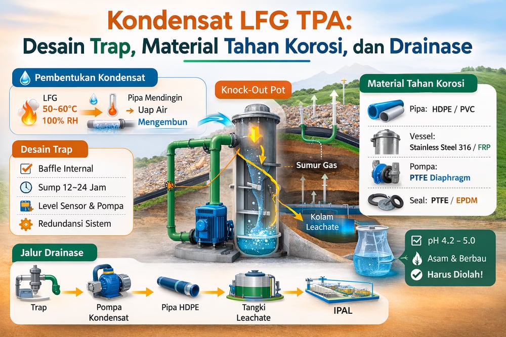
Condensate’s low pH and organics demand corrosion‑resistant materials. For condensate headers and traps, plastic pipe — PVC (polyvinyl chloride), HDPE/PE (polyethylene) — is widely used because it resists acids and is cost‑effective (chemengonline.com; mgs.co.uk; mgs.co.uk). Where metal is necessary, stainless steel (typically 316L) or FRP (fiberglass‑reinforced plastic) vessels are recommended; one review notes vessel metallurgy “is usually stainless steel” for condensate separators (chemengonline.com).
Pumps and internals should avoid metal in the liquid path, favoring PTFE (polytetrafluoroethylene) diaphragms and other non‑metallic wetted parts (chemengonline.com). Valves and flanges are commonly plastic or stainless, with gaskets in graphite/PTFE; elastomers such as EPDM and Viton are specified to tolerate low pH and H₂S. Buried plastic components use fused joints to ensure leak‑tightness and odor control. Carbon steel is generally avoided unless heavily coated or sacrificially protected, as exposed iron will rust rapidly. In practice, many systems mirror wastewater corrosive‑service standards (FRP tanks, HDPE liners), with chemical‑service‑rated pumps sending liquid to plastic headers (chemengonline.com; chemengonline.com).
Conveyance to leachate treatment
Captured condensate is normally discharged into the landfill’s engineered liquid system and treated as part of leachate. Typical practice is to pump each sump or knockout pot to on‑site storage or directly into the leachate collection network, then route the flow to a central leachate tank or treatment plant (iwaponline.com). As one review summarizes, “collected condensate is typically combined with leachate for treatment or disposal” (iwaponline.com).
Blending leverages existing infrastructure: condensate can be co‑treated in aeration or membrane systems — a context where operators often reference integrated membrane systems as part of the leachate plant. Some facilities temporarily hold condensate in a dedicated tank before release if immediate blending would exceed capacity. Industry notes that connecting condensate drains to the landfill’s leachate network can “significantly enhance condensate management” and reduce O&M costs, although some local rules forbid mixing (wasteadvantagemag.com).
Compliance remains non‑negotiable. Regulations require meeting discharge standards; U.S. guidance explicitly forbids draining condensate to sewers (chemengonline.com). The World Health Organization notes that mixing condensate into leachate systems is “an industry practice” (supported by best‑practice guides) (iwaponline.com), and design manuals recommend including condensate in leachate pond sizing. In Indonesia, as elsewhere, the common approach is to pump condensate into the lined leachate collection system; from there it passes through the leachate treatment plant before final disposal (or recirculation). Where pH adjustment is required ahead of blending, operators deploy metered chemical feed via a dosing pump, alongside other supporting equipment.
Data‑driven design checklist
- Expected condensate volumes: Use humidity calculations or empirical factors (≈26 L/hr per 100 scfm LFG; chemengonline.com) and worst‑case cooling. Site data show thousands of liters per day are possible (nepis.epa.gov). Size trap capacity and pump rate accordingly.
- Trap design: Provide low‑point sumps at all header sags and a primary knockout drum upstream of blowers. Ensure adequate volume for emergency (e.g., 0.5–1 day of condensate) and include level sensors and redundant pumps for reliability (wasteadvantagemag.com). In high‑moisture or cold environments, double the sizing.
- Material selection: Use PVC/HDPE pipe and FRP or stainless steel vessels. Specify acid‑resistant pumps and coatings. All wetted metal should be 316 SS or higher. Gaskets and sealants should tolerate low pH and H₂S (e.g., EPDM, Viton). Avoid catastrophic corrosion and pinhole leaks.
- Disposal path: Plan for condensate to enter the leachate collection/treatment system. Install a dedicated force main from condensate sumps to the main leachate header, or a transfer tank. Include flow‑metering if regulatory tracking is needed. Ensure the leachate plant can handle the incremental load (field instruments, BOD, acidity). Many operators test condensate quality regularly (pH, TOC, sulfates) to adjust treatment (iwaponline.com).
Operational reliability and environmental outcomes
Experience shows unresolved “slugs” of condensate can render many wells inoperative (wasteadvantagemag.com). Conversely, well‑sized drip traps and knockout pots, corrosion‑resistant materials, and integrated leachate tie‑ins ensure that even several cubic meters per day are safely removed and treated — preserving gas flow and meeting environmental standards (iwaponline.com; wasteadvantagemag.com).
Sources and further reading
A 2021 Chemical Engineering review provides condensate composition and material recommendations (chemengonline.com). EPA research documents liquid yields (nepis.epa.gov; chemengonline.com). Practical guidance from WasteAdvantage and IWA journals details sump design and disposal practices (wasteadvantagemag.com; iwaponline.com). All figures and claims above are drawn from these sources.
