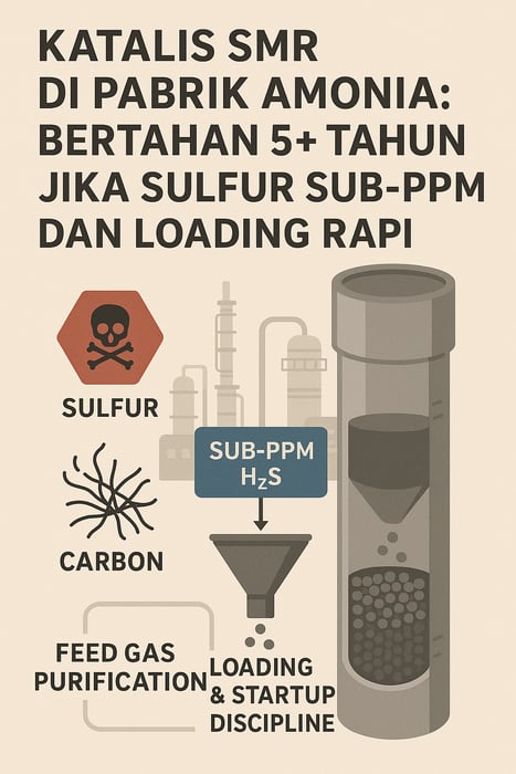
In steam methane reformers, tiny amounts of sulfur or carbon can derail tons of nickel catalyst and millions of Nm³ of gas per day. A disciplined playbook—clean feed, uniform loading, controlled startup—keeps conversion near 99% and campaigns long.
Ammonia plants live and die by their steam methane reformers (SMRs)—reactors that turn CH₄ and H₂O into CO and 3H₂ over high‑temperature nickel catalysts (Ni/α‑Al₂O₃, often with a small K₂O promoter; source: chempedia.info). These units push millions of Nm³ (normal cubic meters) of gas per day through tens of tons of catalyst, so every percentage point of activity matters. Major producers cite typical catalyst lives of 5+ years under ideal conditions (www.syamcat.com).
The catch: nickel deactivates. The quickest culprits are sulfur poisoning and carbon deposition. Even minor contamination—sub‑ppm (parts per million) sulfur or small steam maldistribution—can nudge tube temperatures higher, push methane slip up, and erode yield.
Catalyst deactivation mechanisms (Ni on Al₂O₃)
Sulfur poisoning. Sulfur species—H₂S, COS, and mercaptans—are the most severe poisons for nickel reforming catalysts (chempedia.info; www.sciencedirect.com). Under reforming conditions, sulfur largely appears as H₂S, which adsorbs strongly and forms Ni–S complexes (e.g., Ni + H₂S → Ni–S + H₂; www.sciencedirect.com). Studies note poisoning at just 50 ppm H₂S at 775 °C (chempedia.info), and even sub‑ppm exposure slowly deactivates nickel over time (chempedia.info; www.sciencedirect.com). Commercial practice is to remove sulfur to <0.1 ppm or lower. Nickel poisoning by sulfur is partially reversible with high‑temperature steam purge, but even ppt‑level accumulation remains a concern (www.sciencedirect.com; chempedia.info). Other permanent poisons, including arsenic, lead, and chlorides, are tightly restricted; for example, As must be <50 ppb (parts per billion) to avoid irreversible poisoning (chempedia.info).
Carbon deposition (coking). At reformer temperatures, hydrocarbons can crack to solid carbon (CH₄ → C(s) + 2H₂), and CO can disproportionate via the Boudouard reaction (2CO → C + CO₂). If the steam‑to‑carbon ratio is too low or aromatics slip in, carbon nucleates on nickel and grows as filamentous or encapsulating deposits, blocking pores and sites. The result: reduced conversion and hot spots. Carbon build‑up is cited as “one of the most serious problems” in steam reforming (chempedia.info), and tests on supported nickel identified carbon on spent catalyst as the dominant deactivation factor (pubs.acs.org). Promoters like K₂O and CaO are added to Ni/Al₂O₃ to suppress carbon formation, but cannot eliminate it entirely (chempedia.info).
Physical/thermal effects. Nickel crystallites sinter above ~800–900 °C, shrinking active surface and raising diffusion resistance. Temperature gradients from uneven loading or burner maldistribution can drive local sintering or even tube failure. Impurities in steam—e.g., silica or heavy metals—can clog pores. Uniform loading and temperature control are therefore critical.
Under balanced operation, large SMRs can maintain ~99% CH₄ conversion efficiency. But poor packing drives maldistribution: “each tube has a different exit temperature” and methane slip becomes highly non‑uniform (pdfcoffee.com). In one example, a ±5% flow imbalance between two tubes caused a 40 °C outlet swing and a degraded approach to equilibrium (same source).
Feed‑gas purification train (HDS, amine, ZnO)
A robust purification train is non‑negotiable. Typical flowsheets use hydrodesulfurization (HDS; often NiMo) to convert organic sulfur to H₂S, then amine or physical solvents to strip H₂S/COS to very low levels (<100 ppm), followed by ZnO guard beds that polish H₂S to the ppb range via ZnO + H₂S → ZnS + H₂O at ~300–400 °C. In practice, scrubbing can achieve H₂S <0.1 ppm, with some targets <10 ppb. Sasol’s syngas purification (Rectisol) reports ~0.08 mg S/m³ (~0.1 ppm), which effectively eliminated nickel poisoning in testing (chempedia.info).
Texts emphasize that “ZnO reduces [sulfur] to levels below analytical detection, but even the remaining sulfur will slowly poison the catalyst” (chempedia.info). A survey comment is even starker: “even if sulfur levels in fuels are below 0.2 ppm, some deactivation of steam reforming catalysts can occur” (chempedia.info). Accordingly, many plants include an on‑line H₂S analyzer downstream to catch breakthroughs and switch trains.
Other impurities are handled too: gas is thermally dried (to avoid condensation), and mercury or halides are removed with activated‑carbon traps—an application well served by activated carbon media. Amine systems for H₂S/CO₂ removal (e.g., MDEA) align with solvent packages such as an amine solvent for CO₂/H₂S removal.
Catalyst loading methodology (uniform packing)
Loading determines much of the reformer’s fate. Industry guides recommend careful tube preparation: inspect tubes and support grids, and ensure sleeves or baskets are intact. Place coarse support wedges or a mesh grid at the bottom to prevent washout, then pre‑load an inert zone (e.g., Al₂O₃ balls or spinel rings) to distribute flow and anchor the catalyst (www.slideshare.net).
Controlled fill is vital. Use dropping socks or funnels to deliver pellets uniformly—“use socks to uniformly distribute catalyst at a controlled rate of [≈3 ft] of freefall” (www.slideshare.net). After each meter, check ΔP (pressure drop) to confirm consistent density; low ΔP suggests a loose pack, high ΔP suggests bridging. Pneumatic tapping and manual redistribution help correct anomalies.
Minimize layering effects by avoiding pellet size segregation; for multi‑size beds, add layers gradually to reduce channeling. Poor loading yields uneven tube flows and exit temperatures; in severe cases, some tubes run underfed and others overfed, with hot spots and methane slip (pdfcoffee.com).
Verification matters. Confirm total mass and volumetric fill meet design; densities of ~0.8–0.86 kg/L are typical for Ni/Al₂O₃ types (pdfcoffee.com). Fit hold‑down devices or mesh to prevent fluidization during startup. Purge loaded tubes with dry N₂ and vent to ensure all piping is free of moisture or foreign material.
The impact is measurable. One analysis showed a 10 °C deviation from the equilibrium conversion point when a single tube ran 5% richer than another—forcing higher firing to hit H₂ targets and raising operating cost (pdfcoffee.com).
Reduction and controlled startup sequence
After loading, activation and warmup follow a strict sequence (www.slideshare.net; patents.google.com):
Inert purge and warm‑up. Purge the reformer and steam system with nitrogen (or flue gas recycle) to remove air and moisture. Heat gradually above the steam dewpoint to avoid condensation on the catalyst—condensation can crack pellets (www.slideshare.net). Warm until outlet headers are about 50 °C above the steam dewpoint before introducing steam (www.slideshare.net).
Steam drying phase. Add purified steam alone (no hydrocarbons) at low flow, ramping to ~30–50% of design (minimum ~30%) while maintaining low firing. Keep all hydrocarbon lines isolated (double‑blocked) to avoid inadvertent coking (www.slideshare.net).
Catalyst reduction. Above ~300 °C, introduce a reducing gas to convert NiO to active Ni—often hydrogen or a lean fuel mix. Guidance favors a steam:H₂ ratio of 5:1 to minimize hot‑spot risk; this uses ~14% of normal reformer fuel firing to reach reduction temperatures (www.slideshare.net). Reduction is fastest at high temperature and low steam content (www.slideshare.net). Care is required: uneven H₂ burn can locally overheat tubes.
Hydrocarbon introduction and ramp‑up. After reduction, introduce natural gas gradually. Divert reformer outlet to a compressor or flare, raise flows while monitoring tube temperatures, and progressively reach the design steam:carbon ratio (typically 3–4:1 for ammonia plants) and firing rate. Then close the H₂/bypass and route product syngas to the downstream shift/CO₂ removal units. A Shell patent summarizes the sequence: heat with inert, then “introduce steam and hydrocarbons into the system, stop the inert circulation by closing the valve…and remove hydrogen product” via the compressor (patents.google.com).
Monitoring and ramps. Watch temperatures continuously. Typical tube‑metal ramp limits are 50–100 °C/hr, with some modern designs allowing ~150–170 °C/hr (www.slideshare.net). Avoid oxygen ingress or “catalyst cold spots.” Drain condensate traps diligently—liquid water contacting a hot bed can destroy pellets (www.slideshare.net). Hawkins also cites a case where excessive firing during startup caused catalyst meltdown and tube breach.
Operational economics and planning metrics
Experience shows preventing poisoning and coking is far more cost‑effective than frequent turnarounds. Ensuring extremely low sulfur (sub‑ppm) via staged cleanup has enabled multi‑year campaigns (chempedia.info; www.sciencedirect.com). Disciplined loading and firing prevent hotspot damage and uneven burn‑out. In practice, the combination of meticulous catalyst handling and thorough feed purification typically yields H₂ production rates and catalyst lifetimes at or near theoretical targets—for example, achieving >99% CH₄ conversion in the primary reformer with <1% incremental tube ΔP per year. Conversely, allowing H₂S breakthrough or skipping proper reduction raises methane slip, increases fuel use, and elevates CO byproduct, shortening catalyst life.
Quantitative anchors help evaluate trade‑offs: “50% steam + 5:1 [steam:H₂] uses ~14% of normal fuel for reduction” (www.slideshare.net); “5+ year service life is typical under clean feed” (www.syamcat.com). Poor packing or flow imbalance taxes fuel and output—Hawkins’ notes tie a 5% flow skew to a 40 °C outlet swing and degraded equilibrium approach (pdfcoffee.com).
Sources: www.sciencedirect.com; chempedia.info; chempedia.info; pubs.acs.org; www.slideshare.net; pdfcoffee.com; www.slideshare.net; www.syamcat.com.
