Operators are loading wells with multiple cement barriers and stress-testing each plug to meet tough standards and avoid decades-long leaks. The mandate: cover every flow zone, verify integrity, and aim for “rock‑to‑rock” permanence.
One Gulf of Mexico well dribbled 9–108 barrels/day for 15 years after “abandonment,” its cumulative leakage rivaling a major spill (Environ. Eng. Sci.). In the U.S., the EPA in 2018 put abandoned well count at ~3.11 million, 69% unplugged — each a potential methane pathway (Environ. Eng. Sci.). Even where plugs exist, studies found ~3.4% of the Netherlands’ plugged wells still leak gas (Environ. Eng. Sci.).
That context underpins a hard turn to redundancy and proof. Effective P&A (plug and abandonment) now means multiple independent barriers and documented integrity checks — a stance reflected in API RP 65‑3 and NORSOK D‑010 (PMC; ResearchGate).
Redundant barriers across every zone
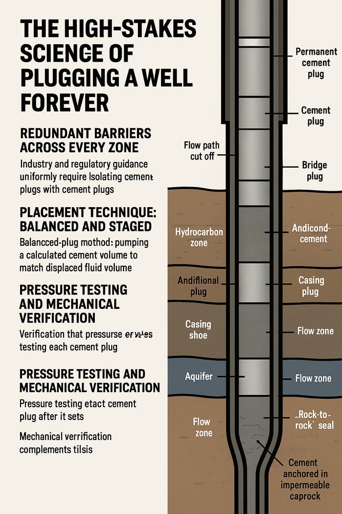
Industry and regulatory guidance uniformly require isolating every permeable zone with cement plugs — NORSOK D‑010 explicitly states that “all zones with flow potential are covered” by cement (PMC). In practice, plugs are set just above each reservoir or aquifer and in any open hole (an unlined bore interval), so each flow path is cut off (PMC).
Typical designs place a permanent bridge plug ~15 m above the top of the hydrocarbon zone, then “cap” it with ~8 m of cement (ResearchGate). Additional plugs go across casing shoes and near-surface formations, so if one barrier fails, the next holds. A bridge plug 15 m above the reservoir plus plug(s) at the casing shoe can overlap cement columns in two annuli (the ring-shaped space between casing and formation), meeting strong zone coverage rules (covering 100% of potential flow zones, PMC) and creating a “rock‑to‑rock” seal — cement anchored in impermeable caprock to prevent future bypass — as emphasized by ExxonMobil (NAP).
In practical terms, operators often use two or more plugs: one high above the reservoir to seal the payzone, one at the casing shoe or next barrier, and often a third near the surface (e.g., above the deepest aquifer).
Placement technique: balanced and staged
The balanced‑plug method (pumping a calculated cement volume so plug height matches the displaced fluid volume left by pulling out the string) has been widely used since the 1980s; balanced placement equalizes hydrostatic pressures above and below the plug to help it stay in place (Environ. Eng. Sci.). Meticulous hole cleaning remains essential because debris or drilling‑fluid contamination can compromise the cement bond (Environ. Eng. Sci.).
In highly deviated or washed‑out sections where cement losses or voids might occur, staged plugging is used. Industry guidance advises placing multiple shorter plugs over a washout rather than one long plug; the bottom plug can be fast‑setting to support upper plugs (Drilling‑for‑Gas).
Plug lengths are typically hundreds of feet. Where old casing is washed out or the interval is highly deviated, length is increased accordingly; one guideline suggests a 13⅜″ casing in a 12¼″ hole would call for roughly 300 ft of cement plug (Drilling‑for‑Gas). The aim is an adequately long barrier above each target zone to account for shrinkage or unexpected channels.
Cement materials, additives, and preparation
Cement plugs use robust, long‑term sealing materials: heavy‑weight cements (e.g., Class G/H with designed rheology) or blends modified for gas‑tightness. Additives such as silica flour and latex are included to reduce shrinkage or improve bond, and fluid additives (lost‑circulation pills, flushes) are used to ensure full displacement (oilfield chemicals). Key placement steps include running any required mechanical plugs (ball or bridge plugs) as casing shoes or anchors, then pumping the cement slurry with careful displacement. After placement, it is standard to circulate or reverse‑circulate to prevent channeling behind the plug. The biggest risk to plug quality is poor preparation — if mud/glaze is not cleaned, the cement may not bond (Environ. Eng. Sci.).
Industry guidelines (API and IOGP) and well‑control standards (OGP Report 501) give detailed mix and placement specifications. The bottom line is to overdesign plugs and volumes rather than underdesign; operators typically include 10–15% excess cement volume when plugging perforations to ensure full coverage, and designs are based on pressure and porosity data. Any unexpected cement loss during placement should trigger additional plugs or contingency measures.
Pressure testing and mechanical verification
Verification is as important as placement. Regulations uniformly require pressure testing each cement plug after it sets. NORSOK D‑010 calls for a low‑pressure leak test (≈1.5–2.0 MPa held for ~5 min) followed by a high‑pressure hold (e.g., 10 min) to confirm no fluid passage (WellCem). The intent is to apply differential pressure on the plug in the direction of flow, if practical (WellCem), with acceptance criteria that account for elastic effects: a stable pressure reading (no rise in leakage) over the test period indicates success (WellCem).
If testing in the inflow direction is not feasible, reversing it is allowed, but a pressure test is mandatory in nearly all jurisdictions to certify the seal (WellCem). Mechanical verification complements this: every plug’s depth is confirmed — typically by “tagging” with wireline or by weight‑testing — and one recommended practice is to apply additional pressure (e.g., 1000 psi over expected formation strength) to see if the plug holds (WellCem). Weight‑on‑plug checks indicate whether the plug is properly contacting formation or has moved, ensuring it is set at the planned location and has not bridged higher.
Cement‑evaluation logs further strengthen assurance. Acoustic or ultrasonic logs (CBL/VDL — cement bond log/variable density log) characterize cement behind casing; newer “smart cement” systems even embed sensors to detect integrity over time. Studies show a combination of good pressure test results and favorable bond log data is a strong indicator of long‑term seal effectiveness, and models show pressure integrity is the most reliable barrier mechanism (Environ. Eng. Sci.). Operators document test results and apply standards (such as API RP 65‑3) for pass/fail criteria, with failed tests triggering re‑plugging or remediation such as milling out suspect cement and repeating the plug.
Permanent seals and regulatory alignment
The goal is permanence — seals lasting decades or longer. As ExxonMobil notes, plugs must be “permanent”: materials and placement should ensure cement (and any expansion or additives) will not degrade over time; that includes choosing caprock strata strong enough to withstand future pressure and placing plugs deep into those layers (NAP). Plug length and cement compressive strength are designed to resist the highest pore‑pressure recharge expected, leaving no loose fluid column or micro‑annuli (tiny gaps) through which gas could migrate.
The rigor has a business logic: strict multi‑plug designs and verification avoid long‑tail remediation costs and sanctions. The approach — follow industry standards and regulatory rules, use redundant cement barriers, and test each plug thoroughly — is supported by global guidance such as API RP 65‑3 (API) and national rules like Indonesia’s Permen ESDM 15/2018 on post‑operation activities (MIGAS), and reinforced by operators’ programs.
Summary and sources
Data‑driven P&A plans allocate ample cement (hundreds of feet of coverage), incorporate best‑practice placement (balanced plugs and contamination control), and require documented proof of seal integrity (pressure tests, tags/logs). The evidence base spans API RP 65‑3 (2024) guidance (API); Indonesia Permen ESDM 15/2018 (MIGAS); Jones et al., Environ. Eng. Sci. (2019) (Environ. Eng. Sci.); Emmel & Dupuy, Data in Brief 37 (2021) (PMC); Chukwuemeka et al., Geoenergy Sci. Eng. 226 (2023) (ResearchGate); NAP workshop proceedings (2024) (NAP); and WellCem industry analyses by Colin Beharie (2017) and Miguel Diaz (2017) (WellCem; WellCem).
