Semiconductor photolithography drains are hot, alkaline, and packed with toxic organics that conventional plants struggle to handle. A dedicated pretreatment line built around advanced oxidation and activated carbon is emerging as the practical fix — and a bridge to reuse.
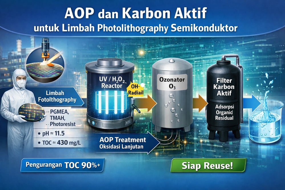
In the world’s most water‑hungry factories, one stream is notoriously hard to tame. Photolithography effluent — the rinse and developer waste from chip patterning — arrives highly alkaline and loaded with solvents, polymers, surfactants, and developers that knock biological treatment off balance. One color‑filter lithography sample clocked pH ≈11.5, with total organic carbon (TOC, a measure of all organic carbon) ≈430 mg/L in a representative rinse stream, turbidity in the hundreds of NTU (turbidity units), and correspondingly high chemical oxygen demand (COD) (patents.google.com) (patents.google.com).
What’s in it? Think propylene glycol monomethyl ether acetate (PGMEA) and ethyl lactate (solvents), tetramethylammonium hydroxide (TMAH, a developer), isopropanol, phenolic photoresist fragments, plus small amounts of metals or pigments from coatings (www.researchgate.net) (patents.google.com). Because TMAH is highly toxic to microbes, dumping this stream straight into a conventional plant risks inhibitory loads and compliance failures. And volumes are not trivial: Korean fabs produce ~177,937 m³/day in total, nearly 20% of industrial flow (www.researchgate.net).
Regulatory thresholds and reuse drivers
In Indonesia (as elsewhere), industrial effluent must meet strict limits on BOD (biochemical oxygen demand), COD, TOC and toxicants. Effluent standards — Government Reg. 22/2021 and Permen LHK 5/2014 — typically cap COD on the order of 50–150 mg/L for industrial discharge. Photolithography waste, with hundreds of mg/L of organics, greatly exceeds those standards if untreated. To protect ecosystems and enable water reuse, a dedicated pretreatment unit is advisable. Globally, water pressure is mounting: one industry report projects semiconductor water use to double by 2035, and cites major firms (e.g., TSMC) reusing more than half of their process water (www.idtechex.com). The same analysis notes SK Hynix boosted its reuse by 51% in 2020–2023 (www.idtechex.com).
Advanced oxidation process options
Advanced Oxidation Processes (AOPs — methods that generate highly reactive hydroxyl radicals, ·OH) include UV/H₂O₂ (ultraviolet/hydrogen peroxide), ozonation (O₃), UV/O₃, peroxone (O₃/H₂O₂), and photo‑Fenton (Fe²⁺/H₂O₂ with UV). For photolithography wastewater, AOPs can mineralize persistent solvents and resist fragments that biological systems cannot (www.researchgate.net).
Evidence is compound‑specific but compelling. In PGMEA tests under alkaline conditions (pH≈10), 60 minutes of O₃ alone removed 62.4% of PGMEA, O₃/H₂O₂ removed 90%, and combined UV/O₃ removed 100% — complete oxidation in an hour (www.researchgate.net). Separately, a UV/H₂O₂ reactor (60 min exposure, UV≈15.6 mW/cm²) followed by biofiltration achieved >95% TOC removal for five of six organics — propylene glycol MEA, ethyl lactate, TMAH, isopropanol, phenol — with only NMP (a tough cyclic amide solvent) resistant (www.researchgate.net).
Reactor configuration and pH control
Practical designs range from UV‑irradiated continuous stirred‑tank reactors (CSTRs — mixed reactors with continuous flow) to plug‑flow loops with peroxide dosing or ozone sparging (patents.google.com). A loop‑through reactor with medium‑pressure UV lamps (15–20 mW/cm² intensity) and H₂O₂ injection can operate at neutral pH to generate ·OH radicals, while an ozone injector paired with UV creates a powerful oxidant mixture (www.researchgate.net) (www.researchgate.net).
pH matters. Den et al. observed that acid or neutral pH (≈6–8) yields effective UV/H₂O₂ oxidation (www.researchgate.net) (www.researchgate.net), whereas Wu et al. found alkaline pH (~10) enhanced ozone‑based oxidation (www.researchgate.net). Given that photolithography effluent often arrives at pH>11 (from TMAH/KOH), partial neutralization may be required before UV/H₂O₂ or to optimize the selected AOP. In practice the design intent is >80–90% COD/TOC reduction before discharge; for example, targeting ≥90% TOC removal — from ~430 mg/L down to <43 mg/L — would likely meet downstream standards under normal dilution, based on literature benchmarks (patents.google.com) (www.researchgate.net).
Engineers commonly pair acid and oxidant feeds with precise metering; a dedicated unit such as a dosing pump supports steady H₂O₂ or pH‑control additions. For the UV stage itself, industrial ultraviolet units serve as the photon source in UV/H₂O₂ or UV/O₃ configurations.
Activated carbon polishing design
Granular activated carbon (GAC) adsorption complements AOP by capturing residual organics after oxidation. EPA’s technology review notes GAC “adsorbs the relatively small quantities of soluble organics…and heavy metals remaining in wastewater” (nepis.epa.gov), and lists aromatic and aliphatic solvents, phenolics, acids, and surfactants among amenable compounds (nepis.epa.gov). Typical design is downflow fixed‑bed with backwashing to control headloss (nepis.epa.gov). In practice, 10–30 minutes of contact time can remove >90% of low‑level organics.
Even TMAH can be addressed: specialized adsorbents show granular/powdered activated carbon can adsorb TMAH, and graphene oxide can achieve nearly double the adsorption capacity of conventional GAC for TMAH (www.mdpi.com). In full‑scale systems, spent GAC is periodically regenerated off‑site or replaced. As the polishing step, a packed bed of activated carbon is a straightforward way to ensure partially oxidized organics and trace contaminants are removed to targets.
Protecting the bed from fines helps sustain run length; a simple cartridge filter upstream of GAC is a common solids safeguard.
Integrated pretreatment train
A robust pretreatment scheme for photolithography wastewater runs in five stages: (1) equalization/settling to buffer pH and loads; (2) pH adjustment to neutralize KOH/TMAH if needed for AOP; (3) an AOP reactor — UV/H₂O₂ photoreactor or ozone contactor, possibly with UV — sized for ~0.5–1 h retention; (4) solids removal — settling or filtration to remove flocculated polymers (a Kurita patent notes flocculating phenolic resins can clarify litho wastewater) (patents.google.com); and (5) GAC polishing in a fixed bed. This sequence is designed to strip >90% of COD/TOC from the lithography stream, with published work showing >95% removal of target solvents in AOP+bio configurations (www.researchgate.net).
Equalization and clarification hardware can be compact; a lamella settler reduces footprint compared to conventional clarifiers while buffering the flow and solids before the oxidation step. For the UV/O₃ or UV/H₂O₂ reactor, medium‑pressure UV intensity and oxidant dose can be tuned to the 0.5–1 hour hydraulic retention target. Downstream, GAC polishing ensures effluent organic levels drop from ~400–500 mg/L TOC at the inlet to “tens of mg/L” at the outlet, so the main wastewater plant receives a low‑strength, more biologically amenable load (patents.google.com).
Performance outcomes and trajectory
Analytically, the pretreatment delivers COD/TOC reduction on the order of 80–100%, with effluent values possibly <50 mg/L, depending on the organics. Complete PGMEA removal has been documented under UV/O₃ for 60 minutes (www.researchgate.net), and Den et al. report virtually all photolithography solvents eliminated (≤35% residual NMP) after AOP+bio (www.researchgate.net). Activated carbon polishing then adsorbs remaining organics, including acids from partial oxidation (nepis.epa.gov) (nepis.epa.gov). The net effect supports regulatory compliance and dovetails with aggressive fab reuse goals noted industry‑wide (www.idtechex.com).
Source notes and citations
Sources: Key data and design benchmarks are drawn from recent studies and reports. Den et al. (2002) demonstrated >95% TOC removal for typical lithography solvents using UV/H₂O₂ (supported by biodegradation) (www.researchgate.net). Wu et al. (2008) quantified PGMEA oxidation (62–100% removal under various O₃/UV conditions) (www.researchgate.net). Adsorption data (e.g., TMAH uptake on carbon) come from Birloaga et al. (2019) (www.mdpi.com). EPA documents inform GAC design and scope (nepis.epa.gov) (nepis.epa.gov), while industry analyses frame the scale and reuse trends (www.idtechex.com). AOP reactor configuration guidance is supported by patent literature (patents.google.com), and photolithography wastewater composition and strength are detailed in patents and studies (patents.google.com) (patents.google.com). These sources underpin the scale and efficacy expectations used in this pretreatment design. References: All data above are cited inline from peer‑reviewed articles, industry reports and official sources. Each inline citation points to the relevant source segments.
