

Semiconductor cleanrooms are engineered to strip air of sub‑micron particles while locking temperature and humidity so tight that wafers and photomasks don’t change size. The result: ultraclean air, stable dimensions—and measurably better yield.
Industry: Semiconductor | Process: Wafer_Fabrication
Semiconductor cleanrooms don’t just move air; they sculpt it. Designers stack three filtration stages to scrub particles down to sub‑micron sizes, drive hundreds of air changes per hour, and hold temperature to ±0.1 °C and relative humidity to a narrow band so a 300 mm wafer doesn’t grow or shrink by more than tens of nanometers. The approach is codified globally (ISO 14644) and locally in Indonesia via SNI‑ISO14644, and it pays off in yield and reliability.
At the front line are graded filters—coarse to fine to HEPA/ULPA—followed by unidirectional (laminar) flow from ceiling fan‑filter units (FFUs). Pressure differentials keep dirty air out; variable‑frequency drives (VFDs) and controls trim energy without loosening tolerances (hvactechnocrat.com).
Three‑stage filtration cascade
Cleanrooms rely on a three‑filter cascade: a coarse pre‑filter (G‑class) on outside air intakes to catch large debris (>10 µm), an intermediate fine filter (ISO ePM1–ePM10, often F‑class) for ~1–10 µm particles, and terminal HEPA/ULPA elements to capture <1 µm particles (schillingengineering.de). That graded approach protects the final filters and equipment; even simple coarse stages reduce the burden on expensive HEPA/ULPA media.
HEPA H13 filters (per EN1822) are certified to remove ≥99.97% of 0.3 µm particles (escolifesciences.com), and ULPA U15–U16 reach ~99.9995% at 0.1–0.2 µm (schillingengineering.de). One industry review notes modern HEPA/ULPA systems “remove particles as small as 0.12 µm” (dryroomsolution.com). Proper staging can multiply HEPA service life by 2–3× versus single‑stage approaches (schillingengineering.de).
In Indonesia, SNI‑ISO14644 guidance explicitly recommends a “three‑stage filtration system (pre‑filter + medium filter + HEPA/ULPA)” in HVAC design (gcccleanroom.com). Final HEPA stages are individually leak‑tested per EN1822, ensuring sub‑micron removal efficiency (schillingengineering.de). Pre‑filters commonly take the form of easily serviceable elements; in many industries that includes cartridge‑style formats (cartridge filters), while cleanrooms reserve HEPA/ULPA media for the terminal stage.
At the point of use, those terminal elements sit in sealed housings in ceiling FFUs; the sealing rigor is comparable to sterile‑service enclosures seen elsewhere (for example, 316L stainless steel housings used in pharmaceutical applications: ss‑cartridge‑housing). Upstream equipment often leverages robust industrial housings to handle recirculation duties (steel filter housings).
Unidirectional flow and air changes
Filtered air flows in unidirectional (laminar) streams from ceiling FFUs, sweeping particles downward and out. A semiconductor HVAC guide describes air “flow[ing] downwards through ceiling fan filter units in a smooth, vertical pattern” to reduce turbulence over process tools (hvactechnocrat.com). Vertical laminar flow around 0.36–0.50 m/s is common over ISO 5/Grade A zones; non‑critical areas may use turbulent flow with recirculation.
Air change rates (ACH, air changes per hour) are extreme by normal building standards. ISO Class 5 rooms typically target ≥240 ACH (gcccleanroom.com), while ISO Class 7 often runs 30–60 ACH. By design, the entire room volume is replaced every few minutes, flushing out particulates; office spaces, by contrast, are often <10 ACH.
Pressure differentials and envelope integrity
Positive pressurization isolates cleaner zones. Standard practice is ~10–15 Pa between adjacent clean areas, and >15 Pa between any cleanroom and non‑clean neighbor (gcccleanroom.com). That outward push prevents unfiltered ingress through cracks; envelope tightness matters because leakage must be overcome by supply airflow.
For context, cleanrooms targeting ISO Class 5 (Class 100) permit only ~3.5×10^3 particles/m³ ≥0.5 µm, so total particle removal must span 4–5 orders of magnitude—achieved by the cascade filters and high ACH (hvactechnocrat.com).
Temperature control and dimensional stability
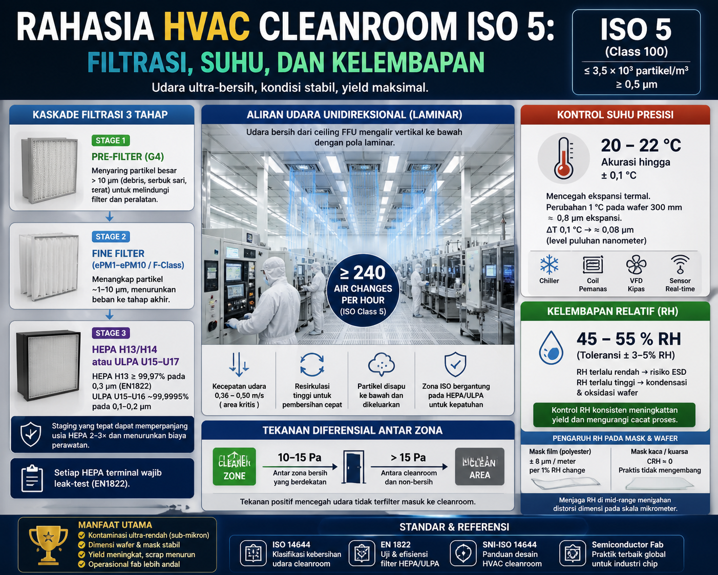
Most fabs hold 20–22 °C, with many managing to ±0.1 °C to prevent thermal expansion/contraction that would distort features (hvactechnocrat.com). Single‑crystal silicon’s coefficient is ~2.6×10^−6/°C; a 1 °C change in a 300 mm wafer yields ≈0.8 µm expansion, so ±0.1 °C limits that to ≈0.08 µm—tens of nanometers, manageable at sub‑10 nm (14644.dk).
Industry experts warn “even small temperature fluctuations can affect microchip performance, leading to failures in product yields” (14644.dk). Controls blend chillers, heating coils, rapid feedback, and VFDs to hold tolerances while saving energy (hvactechnocrat.com).
Humidity control and photomask effects
Humidity (RH, relative humidity) is typically held 40–60% to balance ESD and moisture risks (hvactechnocrat.com). Low RH (<30–40%) raises electrostatic discharge risk; high RH (>60–70%) can drive condensation and oxidation on wafers—both linked to yield loss (dryroomsolution.com). Reviews explicitly link consistent humidity control and fewer moisture defects to a “higher ratio of usable chips” (dryroomsolution.com).
Photomasks and wafers respond differently to humidity. Film‑based masks (e.g., polyester) absorb water and expand by about 8 µm per meter per 1% RH change; glass or quartz masks exhibit virtually zero humidity‑driven expansion (CRH≈0, with CRH being a humidity expansion coefficient) (elveflow.com). One source notes “humidity is probably the hardest… and also has the biggest influence on dimensional changes,” recommending glass masks partly for this reason (elveflow.com).
Indonesia standards and climate constraints
Indonesia’s SNI‑ISO14644 mirrors ISO 14644 for air cleanliness classification and cleanroom qualification (gcccleanroom.com). Typical environmental setpoints are 20–24 °C (±2 °C) and 45–55% RH (±5%), with fabs often tightening these further for sensitive steps (gcccleanroom.com).
The tropical climate “necessitates special HVAC designs” to hold those ranges, often requiring powerful dehumidification (desiccant units) or deep cooling to reach dewpoints as low as −40 °C (gcccleanroom.com). Local codes (e.g., electrical, seismic) apply alongside cleanroom standards.
Energy, controls, and outcomes
High precision has an energy price: cleanrooms use ~25× the energy per m² of ordinary spaces, with HVAC consuming 50–75% of the load (cleanroomtechnology.com). Efficiency tactics—variable air volume, airtight envelopes, heat recovery, and VFD fans—can cut operating costs by 10–20% without compromising ISO Class 5 (hvactechnocrat.com).
The performance returns are tangible. Holding RH within tight limits reduces ESD and moisture defects, delivering a “higher ratio of usable chips” (dryroomsolution.com). Likewise, ultra‑stable temperature minimizes overlay shifts, alignment errors, and linewidth variation. Even at the hardware level, keeping filtration elements properly seated in sealed enclosures is central to sustained performance—a design philosophy echoed across industrial filtration hardware (fiberglass filter housings).
Source validation
Verified data and guidelines were drawn from cleanroom design references and industry reports, including gcccleanroom.com, escolifesciences.com, hvactechnocrat.com, dryroomsolution.com, elveflow.com, schillingengineering.de, 14644.dk, and cleanroomtechnology.com (all URLs embedded inline above).